Sep 23, 2026News & Insights
IEC 61032 Test Probe B vs Probe 11: Jointed vs Rigid Test Finger Explained
Both simulate a human finger, but IEC 61032 Probe B (jointed, 10 N) and Probe 11 (rigid, thrust-applied) test different things. Compare design, force and applications.
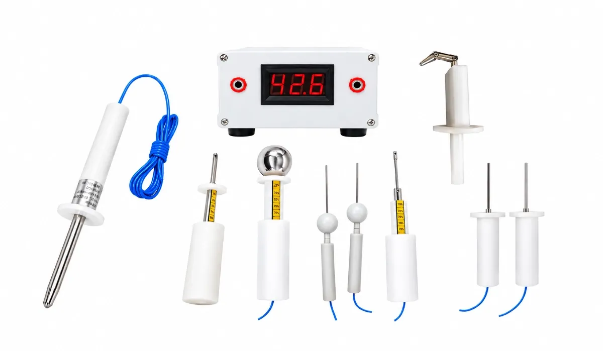
IEC 61032 defines a family of probes that stand in for the human body, and the two most used finger probes look deceptively similar: both have a 12 mm metal finger, an 80 mm tip length and a 50 mm stop face.
The difference is the joint — and it changes what the probe can prove:
• Probe B (Figure 2) has two pivot joints and bends 90° like a real finger. It goes where a finger can go, and it proves that dangerous live parts are accessible.
• Probe 11 (Figure 7) is rigid and straight, applied with a measured thrust. It proves that guards and openings withstand finger-force contact without failing.
Labs that own one but not the other routinely discover the gap at certification time.
Probe B: The Jointed Test Finger
The IEC 61032 Test Probe B is the classic "test finger" of IEC 61032 Figure 2 and IEC 60529 Figure 1:
• Dual-jointed design, bending 90° ± 10° in the same plane — it reaches into gaps and around ledges a rigid tool cannot
• Knurled metal finger Ø12 mm ± 0.1 mm, 80 mm long, for reliable electrical contact detection
• 50 mm baffle plate preventing over-insertion
• Applied thrust 10 N ± 0.5 N — the force of a light finger touch
• Conductive stainless-steel finger (resistance ≤ 0.1 Ω) with insulated handle
How it is used: the probe is inserted and, with the joints, maneuvered in every practical position toward hazardous parts. A contact indicator connected between finger and housing signals any touch. Its familiar certification role is IP2X (and IPXXB) accessibility testing under IEC 60529, plus the accessibility clauses of appliance and electronics standards.
Probe 11: The Rigid Test Finger
• Rigid straight finger, Ø12 mm × 80 mm, with a 50 mm stop face
• Applied with measured thrust, per the product standard's requirement
• Used where the standard demands that dangerous parts stay unreachable and that guards survive the attempt: bezels and openings in the 20–50 mm range, protective grids and barriers
The force-rated variant — the rigid test probe 11 with 50 N/75 N force — applies 10–50 N or 10–75 N depending on the product standard under test (IEC 61032, IEC 60335-1, IEC 60065 family). This is the strength test: the guard must not deform into contact, and the opening must not admit the finger under load.
Side-by-Side Comparison
• Design — Probe B (Fig. 2): Two joints, bends 90° ± 10°; Probe 11 (Fig. 7): Rigid, unjointed
• Applied force — Probe B (Fig. 2): 10 N ± 0.5 N; Probe 11 (Fig. 7): Standard or force-rated: 10–50 N / 10–75 N
• Tests — Probe B (Fig. 2): Accessibility of hazardous live parts; Probe 11 (Fig. 7): Withstand strength of guards and openings
• Reaches — Probe B (Fig. 2): Around ledges, into gaps, like a finger; Probe 11 (Fig. 7): Straight-line entry only
• Typical roles — Probe B (Fig. 2): IP2X / IPXXB accessibility (IEC 60529 Fig. 1), appliance accessibility clauses; Probe 11 (Fig. 7): Thrust tests on openings, grids and bezels; 60335/60065-family strength checks
• Contact detection — Probe B (Fig. 2): Indicator lamp through conductive finger; Probe 11 (Fig. 7): Indicator through conductive finger
Which One Does Your Standard Call Up?
• Enclosure protection (IP code): IP2X accessibility is verified with the jointed test finger — Probe B.
• Household appliances (IEC 60335 family): both appear — Probe B for accessibility, Probe 11 with force where guards and barriers must withstand thrust.
• Audio/video and IT equipment (IEC 60065 heritage, IEC 62368-1): the force-rated rigid finger for strength verification of guards.
• Uncertain which edition applies? The standard's clause names the figure — Fig. 2 means jointed, Fig. 7 means rigid. Match the figure, and note the force the clause assigns.
Ask for calibration documentation with both probes when ordering, and the complete probe range covers the rest of the IEC 61032 family — probes 18, 19, 31, 32, 41 and the accessibility sets. The full selection logic is in the IEC 61032 probes guide.
Frequently Asked Questions
Can Probe 11 replace Probe B for IP2X testing?
No. IP2X accessibility testing requires the jointed finger precisely because it reaches where a rigid tool cannot — a rigid probe passing the opening proves less than the standard demands. Keep the jointed probe for accessibility and the rigid one for thrust tests.
Why is the rigid probe applied with 50 N or 75 N?
Because the failure mode being tested is different: not "can a finger touch it?" but "does the guard survive a finger pressing hard?". The force is set by the product standard's clause, and the force-rated probe delivers it repeatably.
What is the 50 mm baffle for?
It stops over-insertion and simulates the back of the hand: everything behind the baffle represents parts a finger cannot reach. The baffle's presence — and its diameter tolerance — is part of what makes the probe standard.
Why is the metal finger conductive?
The probe is wired to a contact indicator. If the conductive finger touches a live part, the lamp lights and the test fails — the detection is electrical, so the finger's conductivity (≤ 0.1 Ω) is a specification, not a detail.
Conclusion
Probe B and Probe 11 answer two different safety questions with the same finger-shaped tool: the jointed probe asks "can a finger reach the hazard?", and the rigid probe asks "can the guard take the press?". A lab covering product safety standards needs both — and both calibrated, because the force figures in the report are only as credible as the instrument behind them.
Send Top Test the standard and clause you are testing against — contact us for the matching probes with calibration documentation, or browse the full test finger probe range.