Sep 22, 2026News & Insights
What Is Comparative Tracking Index (CTI)? IEC 60112 Testing Explained
CTI measures how well insulating plastics resist electrical tracking under wet contamination. How the IEC 60112 test works — electrodes, electrolyte drops, voltage steps, CTI vs PTI.
An insulating material can pass every flame test and still fail in service — because the failure comes not from fire, but from a slow carbon trail growing across its surface.
The Comparative Tracking Index (CTI) measures that failure mode: how well a solid insulating material resists electrical tracking — the conductive carbonized path that forms when voltage, surface moisture and contamination act together. The test method is defined in IEC 60112 (with ASTM D3638 and UL 746A as the North American counterparts).
CTI matters wherever insulation lives with contamination around it:
• Plugs, sockets and connectors
• Terminal blocks, relays and switchgear
• PCB substrates and coil formers
• Appliance housings around live parts
• EV and new-energy insulation components
What "Tracking" Actually Is
Dust, salt and humidity settle on every insulating surface in the real world. Between two live conductors, that wet film conducts a small leakage current — which heats the surface, dries the film, and leaves behind a carbonized trace. The trace conducts better than the clean plastic, so the current concentrates there, and the path grows step by step until the two conductors bridge: a flashover across a material that was, by every other measure, a good insulator.
Tracking is why a material's bulk properties are not enough — the surface, under contamination and voltage, is what fails.
How the IEC 60112 Test Works
The test places the material in exactly that hostile condition, under control:
• Electrodes. Two platinum electrodes (2 mm × 5 mm faces) press on the specimen at a 60° angle, 4.0 mm apart, with 1.0 N contact force.
• Voltage. An AC voltage — adjustable from 100 to 600 V in 25 V steps — is applied across the electrodes.
• Contamination. An electrolyte of 0.1% ammonium chloride (simulating contaminated moisture) drips between the electrodes: one drop every 30 seconds, from about 35 mm above the surface.
• Watching for failure. The instrument monitors leakage current continuously. A failure is declared when the current exceeds roughly 0.5 A for 2 seconds — meaning a conductive track has formed — or when the specimen ignites.
• Stepping until it passes. The voltage is lowered (or raised) until the highest voltage is found at which the specimen survives the full drop program without tracking failure.
CTI is the highest voltage the material withstands for the full drop test. A higher CTI means better resistance to tracking: materials in the 400–600 V range handle hostile environments; materials below 175 V are limited to benign, dry applications.
CTI vs PTI
The two indices come from the same test and answer different questions:
• CTI (Comparative Tracking Index) — a material property: the maximum voltage the specimen withstands, used to compare materials and to classify them.
• PTI (Proof Tracking Index) — a pass/fail verdict: the material must survive a specified test voltage, the one a product standard demands. PTI is the number certification work leans on.
A datasheet showing "PTI 250" says: this material passed the 250 V proof test. A datasheet showing "CTI 400" says: this material survives up to 400 V in the comparative test. Certification requirements are usually written against PTI; material selection and comparison use CTI. North American practice (UL 746A) converts CTI into Performance Level Categories (PLC) that appear on yellow cards.
The Equipment
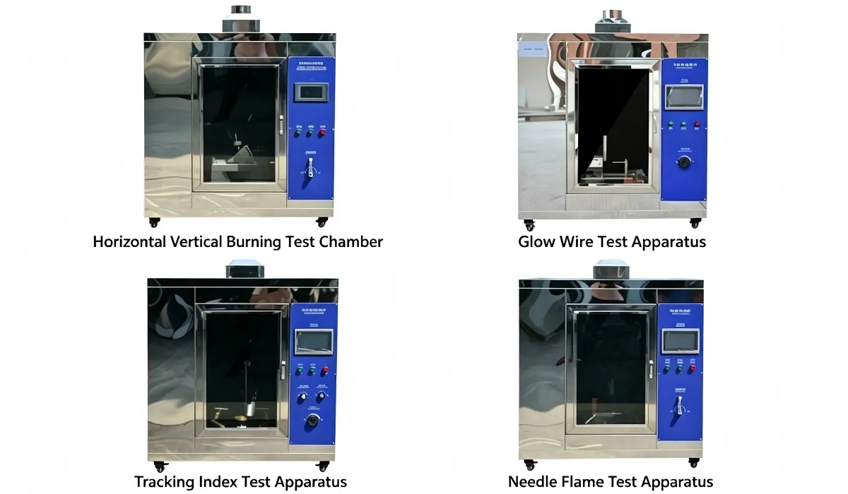
The test lives or dies on three precision details: electrode geometry and force, droplet volume and timing, and fast failure detection. The Top Test tracking index test apparatus (TT-01) delivers them to IEC 60112:2020, GB/T 4207-2022, UL 746A and ASTM D3638:
• 99.9% platinum electrodes, 60° angle, 4.0 mm spacing, 1.0 N ± 0.05 N force
• Peristaltic drip system: 30 s ± 0.1 s interval, 20–23 mm³ droplets, programmable count
• 100–600 V AC supply in 25 V steps
• Automatic failure detection at 0.50 A for 2.00 s, with auto-abort
• PLC + touch screen control, multi-specimen stage for parallel testing, built-in exhaust
It sits alongside the glow wire tester and flame testers as the third leg of insulation safety: flame tests ask how the material burns, the CTI tester asks whether its surface stays an insulator under contamination and voltage.
Frequently Asked Questions
Why ammonium chloride solution?
It is the standardized stand-in for real-world contamination — a controlled, reproducible conductive film. Real dust and salt vary too much between sites to make a repeatable test; the 0.1% NH₄Cl electrolyte gives every laboratory the same wet contamination.
What CTI do I need for my product?
The product standard decides, usually expressed as a required PTI voltage. Materials near live parts in humid or dusty environments typically need higher values than those in dry, sealed assemblies. Check the clause before selecting a resin — a material that molds beautifully but tracks at 175 V cannot be rescued by design.
Does CTI testing damage the specimen?
Yes — a tracking failure carbonizes the surface permanently. Each specimen is single-use, which is why the multi-specimen stage matters for laboratories running material comparisons.
Is CTI the same as arc resistance?
No. Tracking is a surface conduction process under wet contamination; arc resistance measures resistance to a high-energy arc. Both concern insulation failure but simulate different service mechanisms and use different equipment.
Conclusion
CTI answers a question no other test asks: when moisture and dust coat the surface and voltage keeps pushing, does this insulator stay an insulator? IEC 60112 turns that into a number — the highest voltage survived — that material selectors and certification bodies both use.
Send Top Test the material family and the PTI voltage your standard requires — contact us for a quotation, or browse the full burning and electrical safety test equipment range.